-
2. Upgrade the router so it can control servos
 WRT54GL router is not capable of controlling mechanical parts as is. So we need to add a communication port and a servo controller to it. This post describes how to do that. Before you proceed please make sure you have read the Routerbot v1 project outline.
First we need to expose one TTL serial interface that is hidden somewhere in the router + we’ll see an option of adding a regular RS-232 serial interface for debugging purposes.
First of all let’s void your router’s warranty by taking it apart. This post explains how to do that.
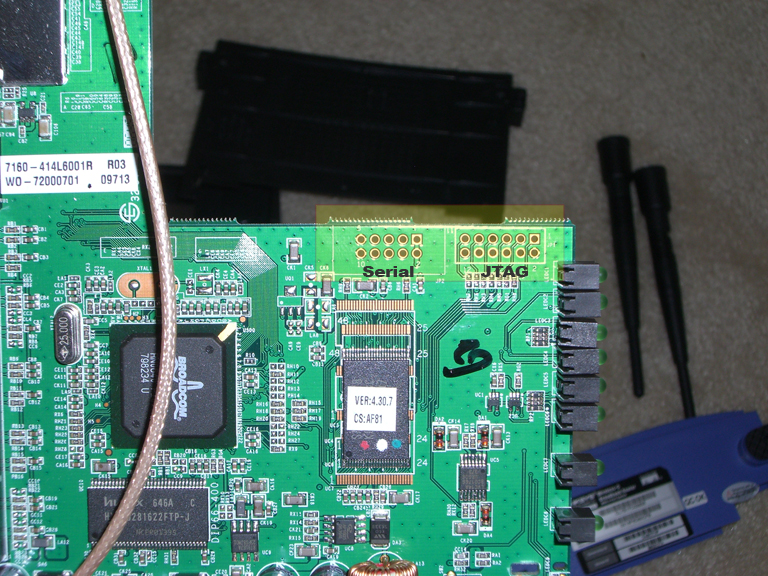
On the video in the post above you saw a 10-pin(well, actually 10-hole) connector that provides two serial interfaces. Grab the 3-wire data cable you bough on previous step and cut it into two equal 3-pin headers. Solder one of those to the 10-hole connector in the following order:
- PIN3 – to red wire, this is serial interface 1 Tx line
- PIN5 – to white wire, this is serial interface 1 Rx
- PIN9 – to black wire, this is ground
Optionally you can also expose and mark four more wires that can be used as a COM0 connection that is pretty useful for debugging purposes. You will be able to see entire boot process and connect to the router even if all its network interfaces are down.
- PIN2 – +3.3V
- PIN4 – Tx
- PIN6 – Rx
- PIN10 – Ground
This separate post how to use those 4 wires to get serial console to the router. I highly recommend adding this port for debugging purposes as it will safe you a lot of time during the router reflashing.
Well done! Now you can take a look at your SSC-32 servo controller and find 5 pins related to serial port. In the manual that comes with the controller they are marked as 13. Take out two jumpers that connect 4 of those pins (save them for the future) and plug in 3-wire cable to the 3 pins in the row. Make sure that black wire goes to the ground, Tx goes to Rx and Rx goes to Tx via 12K resistor in series. Also put 18K resistor between the ground and Rx line from the router. The problem you’re solving with these resistors is incompatibility between SSC-32 TTL (5v) and WRT54GL LVTTL (3.3v). Here is a nice article on sparkfun about other methods of solving this problem.Now, when you got familiar with those 3 wires unplug SSC-32 controller, put it aside and let’s proceed to the next step before we start testing the system and reassembling the router.
5 Responses to “2. Upgrade the router so it can control servos”
 RSS
RSS Contact Us
Please can you explain more detaily how you solve the voltage conversion problem? Each Rx and Tx connection of modem are connected to 12k resistor each one? The 18k resistor are connected to both ground and rx? isn’t a short circuit?
I and my friends are trying build this robot for a brazilian student project, if you can help we would be very grateful.
Thanx in advance and sorry for bad english =)
Ken,
I used the schema known as “voltage divider”. One of the best explanations of how it works can be found on wikipedia. And Sparkfun describes how it is applicable to serial interfaces voltage conversion best. Also on sparkfun website you can buy prebuilt adapter.
Andrey
Hey Andrey, i didn’t get it. First connect the pins 3 ,5 and 9. then optionally connect the pins 2, 4, 6 and 10. In the post only the pins 2, 4 ,6 ,10. That’s a bit confusing, where will i connect the pins 3, 5 and 9. I’m sorry for asking, I’m just so interested in your project which is very amazing.
PIN3 – to red wire, this is serial interface 1 Tx line
PIN5 – to white wire, this is serial interface 1 Rx
PIN9 – to black wire, this is ground
On your ssc-32 controller all I see is violet blue and yellow no red white and black wire?
Only this part is giving me problems (communication between router and ssc-32) everything else seems easy to do.Some scheme could help us a lot if you cannot make a photo.We are grateful for sharing this great project with us.
Hi acro,
You’re right, I replaced the cable later and didn’t update the text. Please use the Tx/Rx/Gnd labels to connect wires properly, not the wire colors.
Andrey