-
4. Test basics and assemble your robot
 Ufff… the most critical part of your routerbot is done. Now it is time to do basic tests and assemble whatever you have done. Before you proceed please make sure you have read the Routerbot v1 project outline. Please read the assembly instructions as a set of ideas, not as a manual. I’m 100% sure you can build a better robot using better parts. I already saw a very impressive tracked routerbot that is way more robust then this “Mr. Shiny Wheels”. Another robot that uses the same idea of router as the brain was built on top of R/C toy truck. Possibly you can invent even better implementations, like hovercraft or submarine. Think creatively!
It is a good idea to test your work before you assemble your router back to its original form. The tests are pretty basic and listed below. . You can also download that manual from lynxmotion website.- Attach continuous rotation of servos to PWM connectors 0 and 1 and regular servos to connectors 4 and 5 on your SSC-32 servo controller
- On SSC-32 connect jumpers VS1=VS2 (#3) and VL=VS (#5) as it is described in the manual that comes with SSC-32.
- Connect the 3-pin header that comes from the router to TTL serial port (#13) on the controller. Make sure you’re connecting black wire to the ground.
- Connect the battery to the servo controller terminal VL (#4)
- telnet or ssh to the routerbot
- cd /routerbot
- ./test.sh
When you run the test script the servos should start moving somehow (take a look at the test script to see what it is supposed to do). To stop them just run “./stop.sh”. If servos are moving then you can start assembling your router. The assembling process is relatively simpler comparing to taking it apart. You will also need to make a hole in the router enclosure to pass the wires from serial connector. You can do this where it is shown on the picture or you can chose your own design for the parts layout. For instance if you have implemented serial port 0 for debugging purposes you can combine it with a TTL-RS232 adapter and install inside the router.
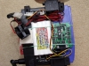
Wire to SSC-32
If servos are not moving then something went wrong. Check the SSC-32 manual for possible mistakes you made (especially the way you connected the servos to the controller, black wire should go to the ground pin). Check that the cable that comes from the router is connected correctly. Check that your wires are connected as it is shown on this picture and that all jumpers are set as shown on the picture. If nothing helps try connecting SSC-32 to your computer and testing it with LynxTerm – a free tool provided by LynxMotion exactly for testing purposes. If LynxTerm is unable to communicated with your SSC-32, well … I don’t know exactly how did this happen, but your servo controller looks not quite alive.
SSC-32 wiring and jumpers in routerbot
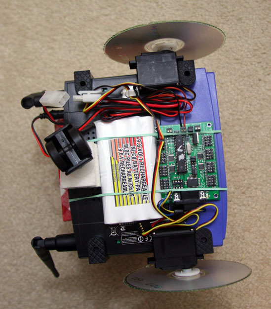
Once you assembled the router invent the layout for overall system or use mine which is shown in the project outline. Here are couple ideas:
- I used two-sided adhesive tape + plastic straps to attach the continuos rotation servos. That worked pretty well, but looked not so well.
- The CD disks are connected to the servos using horns which you will get installed on the servos if you order them from Lynxmotion + two-sided tape + two screws. Make sure that the disks are well aligned and if not then adjust them byt unscrewing the screws a little bit.
- The controller, the battery and the wires are secured primarily with the rubber bands. Bad idea. Better use two-sided adhesive and plastic straps or build something even more robust.
- To attach the coaster wheel I used some piece of foam plastic I found in some packaging. But it doesn’t hold the wheel well, so in addition to that I used plastic bottle cup (see the picture)
- The CD disks used as wheels have really bad traction, especially on carpet. To improve it put small dots of glue around the disk (see picture).
This is basically it. In the photo gallery you can find more pictures of the Routerbot v1.
3 Responses to “4. Test basics and assemble your robot”


 RSS
RSS Contact Us
Andrey,
how much voltage will i need for the router itself? in ur case, u are using 9.6V.. is dat for the RS-232 alone??
Hey Andrey, can I use other servo controller. Or just the SSC-32 servo controller?
Hello Cedrick,
If you’re using not an SSC-32 controller it most probably has command set and you will need to patch the sources in order to support it. Besides that any servo controller should work fine.
Andrey